

Exterior Wall with Water Table
Sep 20, 2022A common request from both the CONTRABIM Membership Community as well as the YouTube Community, is how to create an exterior masonry wall with adjustable water table.
A water table is usually a stone or masonry separator trim between a lower finish, and upper finish. Typically the lower finish will be natural stone or brick, and the upper finish a siding or stucco finish.
Ideally, the goal for building a wall like this in Archicad would be to have the water table (separator trim) be flexible and dynamic, and able to be moved up and down depending on the particular section of the wall.
In this video tutorial, we'll explore how to create a complex profile with water table that can be adjusted to different heights, to fit a wide range of applications.
Step by Step Instructions
To create an exterior wall with water table, as shown in this video, we first need a composite structure or complex profile that represents the general wall makeup, including exterior finish, backing and water protection layers, framing and interior finishes.
Once we have the typical wall buildup (without water table), we can then create a new complex profile that we'll continue to edit with new water table feature.
- Create a base composite structure
- Capture composite structure with Complex Profile Tool and Adjust Nominal Width
- Add skin thickness modifiers (optional)
- Add skin top/bottom modifiers (optional)
- Split exterior finish at a specified point (2'-6" as shown in video)
- Model in water table feature (stone as shown in video)
- Create Offset Modifier to establish water table height
- Create Offset Modifier to FIX water table thickness
- Create top side exterior finish
- Add Final Modifiers
- Adjust Opening Reference, and enjoy!
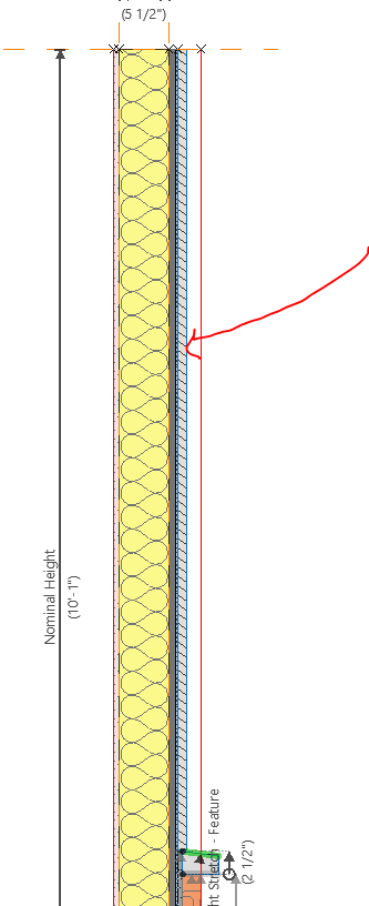
Step 1- Create base composite structure.
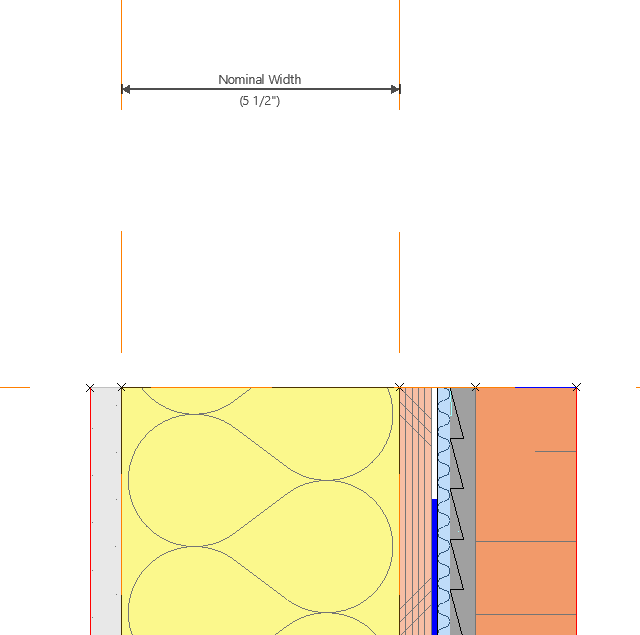
In this example, we started with a composite structure with adhered stone, over mortar with a rain screen mat as shown in this image below.

Step 2 - Capture Composite Structure with Complex Profile
By selecting your placed composite wall, you can activate the Profile Manager and "CAPTURE" the settings, which will take a snapshot of the wall as drawn (including height), into a new custom profile.

Newly created custom profile, from the captured composite structure
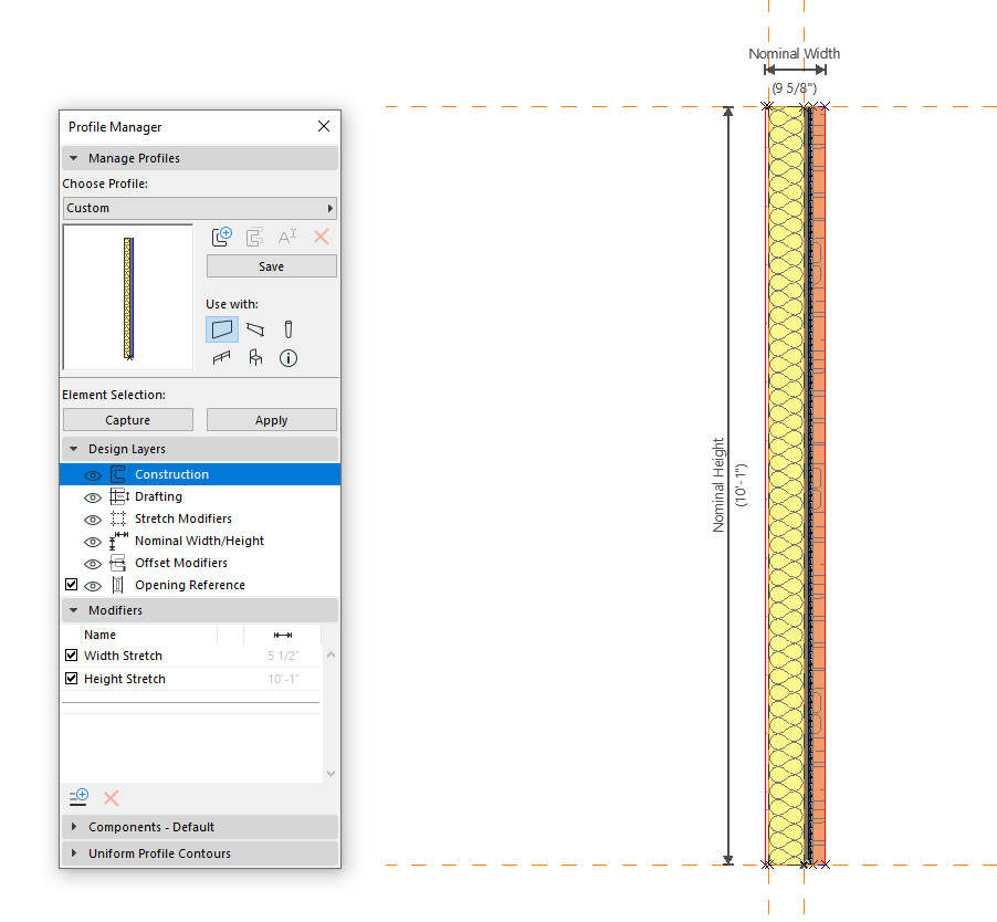
Adjust the nominal width to stud width is our standard practice, so you can quickly adjust stud size.
At this step, it's good to SAVE YOUR PROFILE!
Step 3 - Add Skin Thickness Modifiers (Optional)
If you'd like to be able to change the skin thicknesses, you can add offset modifiers for each skin.
We typically work from the inside out, starting with the first layer (sheathing).
For this method, we use a NODE to EDGE modifier, where the node is the inside point, and the edge is the outside face of the skin.
CAUTION! IMPORTANT NOTE!!!
You must also add the inside edge of the next skin in order for this to work. So for each skin thickness, add the related skin, and the adjacent skin edge for the next one. Continue this all the way through for each skin to create a fully dynamic profile.

Step 4 - Top and Bottom Offset Modifiers (Optional)
You can also create modifiers to push skins up and down. This is not required, and will have to be reworked down the line after you create the water table and top finish, so best to skip this until the end!
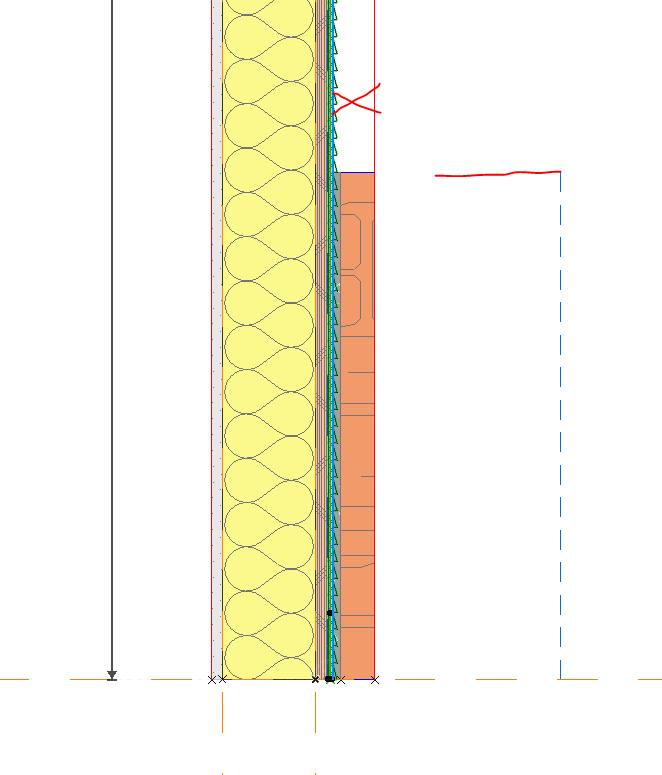
Step 5 - Split exterior finish at a specified point
In our profile, we split the exterior stone skin, and the mortar backing at a height of 2'-6". We create a line to make sure we got this exactly right.
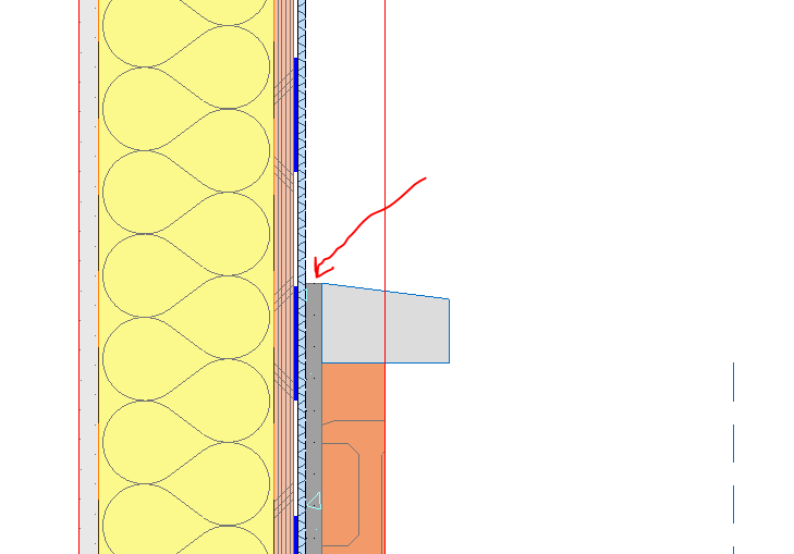
Step 6 - Model New Water Table
The next step is to model in the material fill for the new water table. We chose a 4"x2.5" profile, and adjusted down the exterior 1/2"
We also adjusted the mortar backing up to the top of the water table as well.
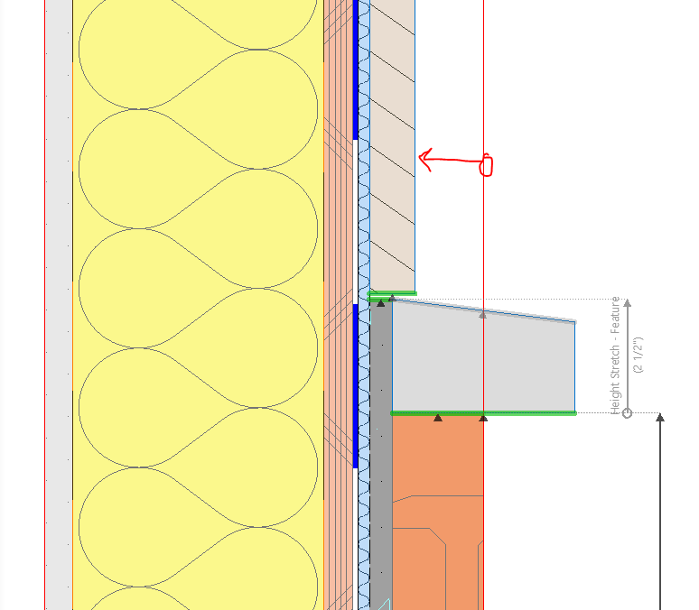
Step 7 - Create Offset Modifier to Establish Height
We created a new modifier called "Height Stretch - Mid Point", which is generic enough that we could use this in several different similar profiles.
Note - This is a node to edge modifier type. We create the first one, and then add additional edges.
The key here, is to start with our base elevation established from the bottom of our framing member, so we use the node that anchors our wall.
We then assign it to the 3 different edges we want to associate with this modifer.
1. The bottom of the water table.
2. The top of the stone veneer
3. The top of the mortar.
All three of these will move when changing the modifier. Hit save and test it out for yourself!

Step 8 - Create offset modifier to establish water table height.
You may have noticed when testing your profile and modifier after step 7, the water table was still fixed to it's position.
In order to get the feature to move up and down with the first offset modifier we created, we must fix it's height!
We can do this by creating a second modifier, that locks the top surface between two nodes.
NOTE! - This is a different type of modifier. It is a NODE to NODE modifier, which is created with 3 clicks plus a direction, as opposed to 2 which we did in the previous step.
Click 1 - First base node.
Click 2 - Second top node.
Click 3 - Edge to be fixed/adjusted.
Click 4 - Specify the direction.

By creating this second offset modifier, we should now be set. Go test it out in your 3d view! If all is working correctly, proceed to step 9. If not, go back and check your modifiers to make sure you have the right points.
Step 9 - Create New Exterior Finish for the Top Side
In this example, we've added in the new top finish as wood siding. We gave it a 1/8" gap to the top of the water table.
Step 10 - Add top finish bottom edge to offset modifier.
In this next step, in order to fix the top finish (siding) to the water table offset modifier, we need to add the bottom edge. Select the original modifier we created, and then add the bottom edge to assign it to move in the same direction as the rest of the assembly! Save and test it out!

Step 11 - Adjust opening reference line.
When placing windows and doors into your wall, you'll want to determine the opening reference line. In this case, you could either use the face of the stone on the base, or the face of the siding on the top side. In most cases, you'll likely want to use the thinner of the two, which would be the siding.
You should now have a fully functional exterior wall with water table!
Do you want more Archicad Training, Templates and Discussion?
Consider becoming a member of the CONTRABIM Membership Site and Community!
Learn more here

Stay connected with news and updates!
Join our mailing list to receive the latest news and updates from our team.
Don't worry, your information will not be shared.
We hate SPAM. We will never sell your information, for any reason.